Failure is Not an Option
An investigation into weld failures in duplex stainless steel flowlines.
Oil and gas pipeline operators often struggle with a bewildering array of factors when it comes to the reliability and safety of their pipelines. This is especially prevalent when the fluid being transported is corrosive and/or at high pressure, or close to people and/or environmentally sensitive areas. Although the risk can be mitigated by selecting the corrosion resistant material, there will always be a sacrifice on the overall cost. In most cases, an ideology increasingly agreed by operators, contractors and owners is to use carbon steel (CS) – for economic reasons. However, the use of CS requires careful management. This scenario eventually leads to careful CAPEX/ OPEX comparisons to select the most suitable choice during the design stage. For highly corrosive environments, corrosion-resistant alloys (CRAs) – in particular duplex stainless steel (DSS) – remains the most cost-effective option. This is because the risk of corrosion failure on CS pipelines is high and the use of corrosion inhibition with CS is often either impractical, costly or poses too high a risk.
Duplex Stainless Steel
DSS was first introduced to the oil and gas industry in the late 1970s when it was selected for natural gas pipelines. At that time, this selection provided a critical commercial breakthrough for Duplex 2205 (UNS S32305/S31803). It paved the way for the acceptance of Duplex 2205 into not only the oil and gas industry, but also into many other industries. As such, DSS material also finds applications in seawater cooling, fire protection systems, topside and subsea production pipe work (apart from flowlines and pipelines). However, this presupposes that all items in the bill of materials are consistently and repeatedly processed, heat treated, pickled, passivated, welded, installed, commissioned, operated, maintained and deployed in environments within the limits of their application range. With over 40 years of wide scale use of this alloy by the oil and gas industry, the overall experience has been good. However, problems can intermittently recur and drastically affect the ‘fit and forget’ philosophy, besides denting the operational excellence. One such high profile and recurring problem has been discussed in this article.
"The breakthrough occurred when optical emission spectroscopy (OES), combustion analysis"
Material Use and Failure History
DSS pipes are joined by welding – which needs special controls to achieve the required quality, properties and corrosion resistance. Failing to control welding correctly can result, in the worst case, in catastrophic failure and loss of life. The DSS pipe material under consideration has been used in flowlines for various wet gas production and reservoir wells since 1984 in the Middle East. For these gas fields, the produced and imported gas is fed and processed in the plant to remove heavier hydrocarbons and water. The heavier hydrocarbons are separated to form condensate liquid. This condensate is stabilised and transported through pipelines. The gas produced from the field is exported through pipelines to a compressor station. Excess available gas (imported) from the gas network is injected in the reservoir and retrieved/produced when required. In general, gas is compressed and injected into the reservoir for storage (in the import mode) and retrieved, processed and transported to a compressor station for distribution (in the export mode). DSS pipe material was first installed at the wells in question in 1984 and was in service for two years. In 2004, the material was reused as another production flowline and was in service for a further six months. In 2016, the pipe material was recovered to construct a different flowline for connection with the well. As part of this task, radiography tests were performed on 26 girth welds. Seven of these girth welds were identified with internal corrosion and pitting corrosion near the heat affected zone (HAZ). However, no defects or flaws were identified on the parent material. The fluid being transported was sour wet gas with high chloride content (2000 ppm). The flowline operating temperature was 66˚C with 103 barg operating pressure. The possible internal damage mechanisms investigated for DSS flowline welds were intermetallic phase precipitation, stress corrosion cracking (SCC) and chloride induced pitting corrosion. The tests performed during the investigation included chemical analysis, pitting resistance equivalent number (PREN) calculation, mechanical tests (hardness, tensile and charpy), microstructural analysis, macro analysis, ferrite count measurement, scanning electron microscope (SEM) analysis and energy dispersive spectroscopy (EDS) analysis, as well as a general visual examination.
Investigation
The results indicated anomalous behaviour of the HAZ and weld root areas. The test material was found to have acceptable tensile, hardness and chemical tests at the parent and weld cap areas, but unacceptable test results at weld root and HAZ areas. The pitting corrosion was observed only at the root side within the defected girth welds. This justified a detailed microstructural analysis at all the locations, though no signs of sigma or chi phases were evident in the microstructural analysis.
The breakthrough of the failure investigation occurred when optical emission spectroscopy (OES), combustion analysis and positive material identification (PMI) analysis showed the weld root of SS309 material and not of DSS UNS31803. Additionally, the calculated PREN value was of SS309 material at weld root side. The microstructural analysis revealed the typical weld root morphology of SS309 with carbides and dendrites precipitating in the interdendritic regions. Close up review of SEM examinations revealed the existence of cleavage facets within the damaged austenite islands, in addition to slip-line formation and ductile tearing.
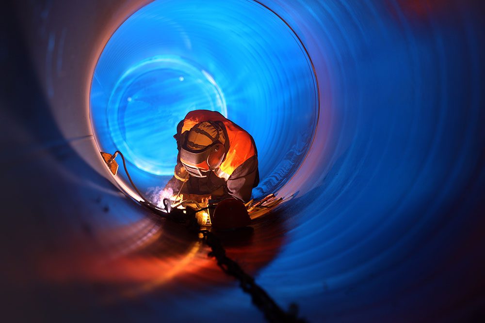
The type of welding involved during the whole process was gas tungsten arc welding (GTAW). Generally, GTAW gives very clean weld metal with good strength and toughness. Mechanisation has substantially increased the efficiency of the process such that it has been used in applications including cross-country pipeline construction. Gas shielding is part of the GTAW process. Generally, pure argon is used – although argon/helium mixtures have given some improvements by permitting faster travel speeds. Nitrogen, a strong austenite former, is an important alloying element, particularly in the super/hyper duplex steels, and around 1 – 2% nitrogen is sometimes added to the shield gas to compensate for any loss of nitrogen from the weld pool. Nitrogen additions will, however, increase the speed of erosion of the tungsten electrode. Purging the back face of a joint is essential when depositing a GTAW root pass. For at least the first couple of fill passes, pure argon is generally used – although small amounts of nitrogen may be added – and pure nitrogen has occasionally been used. EDS analysis did not show any nitrogen content within the weld root side.
Even though DSS is stronger, it does have some drawbacks with respect to welding. Conversely, it does have better corrosion resistance in chloride containing environments than the austenitic range (300 series). Welding controls must ensure that the weld deposit matches the ferrite/austenite ratio of the parent material; excess austenite will make the alloy weaker and excess ferrite will make the alloy more susceptible to hydrogen cracking (subject to all other parameters kept constant). Despite these shortcomings, the strength of these steels and the superior corrosion resistance does make them a natural choice for flowlines where the corrosion resistance is paramount. DSS materials perform satisfactorily in sweet, sour and chloride containing environments (within the limits prescribed by different standards). Experience suggests that the problems most typical of duplex stainless steels are associated with the HAZ, not with the weld metal. The HAZ problems are not hot cracking but rather a loss of corrosion resistance and toughness.
Conclusion
Overall, the probable root cause for the weld failure was identified as being the inappropriate filler wire (SS309), utilised for the root side welding facing a corrosive chloride-containing sour service environment. Additionally, there was also suspicion about incorrect back purge gas quality control during original construction resulting in a locally diminished passivation layer at the root side. The use of wrong filler material was an oversight of the QA/QC personnel involved during the welding operation, as both SS309 and ER2209 looked similar in appearance at that time. Overall, this investigation and the expensive task of DSS pipes ‘cut and replace’ exercise proved to be a valuable lesson to all the parties involved for strict adherence to welding procedure specification and procedure qualification record during the welding operation. Moreover, the remaining flowlines with similar weld history were subjected to thorough inspection and weld repairs where necessary.

